Plastic injection molded parts.
Useful tips for designing plastic injection molded parts.

Wall thickness
The thickness of the part has a significant impact on many of its characteristics, including mechanical properties, visual appearance, moldability, and economic perspectives.
The optimal thickness is often a delicate balance between strength, weight reduction, durability, and cost. Therefore, it should always be carefully considered during the design phase to avoid tooling changes and challenges in later production stages.
For simple flat walls, an additional 10% thickness can increase wall stiffness by approximately 33%. However, increasing the thickness adds extra weight, prolongs cycle time, and increases material costs. Therefore, it is worth considering if there are other geometric features that can provide reinforcement to the part, such as ribs, curves, and grooves. These features can add extra stiffness at the expense of a smaller increase in weight, cycle time, and/or cost.
Flow Leaders
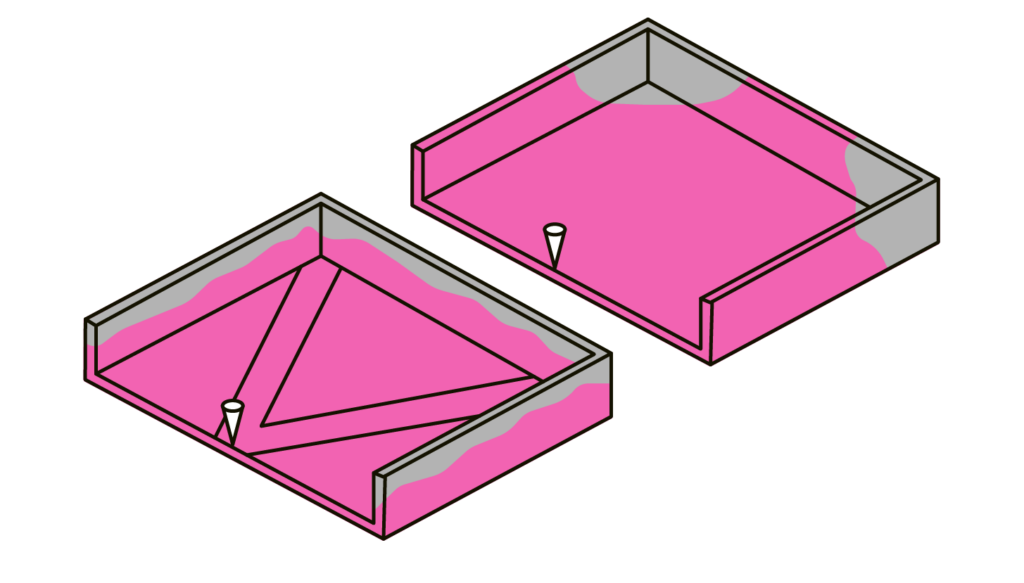
Flow leaders, also known as flow paths, are implemented in plastic design to optimize a more even distribution of plastic within the mold, especially when there is a long distance from the inlet to the outer corners of the part. They can
- Enhance flow: Flow leaders help facilitate the smooth flow of molten plastic throughout the mold cavity, reducing the risk of flow imbalances and ensuring consistent filling.
- Minimize warping and sink marks: By promoting balanced filling, flow leaders can help prevent issues like warping and sink marks that can occur due to uneven cooling and shrinkage of the material.
- Reduce part defects: Properly designed flow leaders can minimize common defects such as air traps, voids, and short shots by ensuring complete cavity filling and preventing material hesitation or stagnation.
- Optimize cycle time: Well-placed flow leaders can improve the overall efficiency of the injection molding process, reducing cycle times by enabling faster and more uniform filling.
To achieve the best results using flow leaders, the flow leader should extend from the inlet and travel without obstructions along its path.
If a mold flow analysis indicates that the material is being distributed asynchronously within the mold, implementing a flow leader can optimize the plastic flow to areas that are filled later in the process.

Med og uden Flow Leaders

Med og uden Flow Restrictors
Flow Restrictors
Flow restrictors are areas in the plastic where the material thickness is reduced. This can be to modify the filling pattern as seen by a mold-flow analysis, to reduce the risk of air bubbles in the part, to reduce the risk of coalescence seams.
When implementing flow restrictors/narrowing of flow paths, remember that;
- A flow restrictor is most effective if it extends across the entire flow path.
- Lengthening/shortening a restrictor can increase/decrease the flow of the plastic.
Ribber
Size
Generally speaking, greater strength is achieved with taller ribs. To avoid problems with filling the mold, ventilation and exhaust, it is a rule of thumb that the height of the rib should not be higher than three times the width of the rib where it is attached.

Thickness
There are many factors that come into play when choosing the right thickness for a rib. Some of the things to take into account are that relatively thick ribs can cause suction and cosmetic challenges on the back of the wall they sit on.
The degree of suction depends on, among other things of the material, the thickness of the rib, the surface structure, the color of the material, location in relation to the inlet and a number of process-related parameters. Eg. is it easier to see suctions on a polished surface versus one with a rougher texture.
Location and number
Be aware of the placement and number of ribs used to avoid exacerbating the challenges that the ribs were supposed to solve in the first place. For example, ribs added to stiffen the article may result in an article that is so stiff that it cannot absorb shock without breaking.
In the same way, a grid of ribs can cause difficulties when cooling the mold and “warpage”. Ribs should therefore be carefully considered in the initial design, so that they are only used where they have a function.
Thickness

The material thickness has a great influence on many of the party’s characteristics, i.a. the mechanical properties, the visual expression, casting possibility and economic perspectives.
The optimal wall thickness is often a fine balance between strength versus weight reduction versus durability versus cost. Therefore, this must always be considered carefully in the design phase, to avoid tool changes and challenges with casting during later production.
In the case of simple flat walls, an extra 10% wall thickness represents approximately a 33% increase in the wall’s stiffness. Increasing the wall thickness adds extra weight, increases cycle time and material costs. Therefore, consider whether there are other geometric features that can stiffen the item – such as ribs, curves and grooves. These features can add extra stiffness at the cost of a minor increase in weight, cycle time and/or cost.
Flow Leaders

Flow leaders are “flow paths” that are implemented in the plastic design. They optimize a more even distribution of the plastic in the mould, e.g. if there is a long distance from the inlet to the outer corners of the workpiece. They can;
- Balance an uneven distribution of the plastic in asymmetrical parts.
- Adjust the fill pattern.
- Reduce the risk of suction in areas with greater wall thickness.
- Reduce the risk of extra fusion seams.
To achieve the best result using flow leaders, the flow leader must extend from the inlet and away without obstacles in the way.
If you have a mold-flow analysis where the material is distributed asynchronously in the mold, it may be that a flow leader can optimize the plastic flow for the areas that are filled most recently.
Flow Restrictors

Flow restrictors are areas in the plastic where the material thickness is reduced. This can be to modify the filling pattern as seen by a mold-flow analysis, to reduce the risk of air bubbles in the part, to reduce the risk of coalescence seams.
When implementing flow restrictors/narrowing of flow paths, remember that;
- A flow restrictor is most effective if it extends across.
- The material thickness should preferably not be reduced by more than 1/3 in materials with a high shrinkage percentage and 50% in materials with a low shrinkage percentage.
- Lengthening/shortening a restrictor can increase/decrease the flow of the plastic.
Ribber

Size
Generally speaking, greater strength is achieved with taller ribs. To avoid problems with filling the mold, ventilation and exhaust, it is a rule of thumb that the height of the rib should not be higher than three times the width of the rib where it is attached.
Thickness
There are many factors that come into play when choosing the right thickness for a rib. Some of the things to take into account are that relatively thick ribs can cause suction and cosmetic challenges on the back of the wall they sit on.
The degree of suction depends on, among other things of the material, the thickness of the rib, the surface structure, the color of the material, location in relation to the inlet and a number of process-related parameters. Eg. is it easier to see suctions on a polished surface versus one with a rougher texture.
Location and number
Be aware of the placement and number of ribs used to avoid exacerbating the challenges that the ribs were supposed to solve in the first place. For example, ribs added to stiffen the article may result in an article that is so stiff that it cannot absorb shock without breaking.
In the same way, a grid of ribs can cause difficulties when cooling the mold and “warpage”. Ribs should therefore be carefully considered in the initial design, so that they are only used where they have a function.


